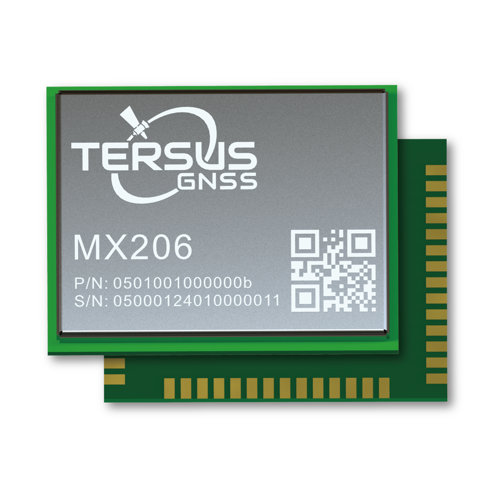
GNSS OEM Integration
MX206 provides multi-frequency GNSS PPP/RTK positioning for embedded platforms. Plan power, interfaces and receiver configuration for the integration.



Provide position and attitude inputs for robots, vehicles and UAVs. Navigation, obstacle avoidance and safety depend on the complete platform and its sensors.
OEM GNSS, inertial sensing, heading, antennas and corrections as inputs to integrated platforms.
MX206 provides multi-frequency GNSS PPP/RTK positioning for embedded platforms. Plan power, interfaces and receiver configuration for the integration.
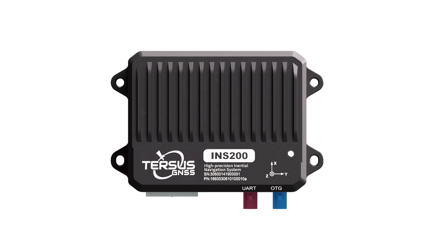
INS200 combines GNSS and inertial sensing. Inertial drift and installation affect performance when satellites are obscured; indoor operation needs an appropriate sensor strategy.
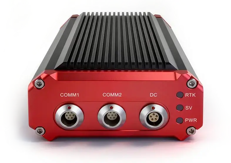
David30-D supplies GNSS position and heading to the platform. Validate antenna placement, baseline geometry and the correction input.
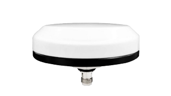
AX4E07 is a multi-frequency GNSS antenna for integrated positioning hardware. Select the antenna and mounting arrangement for the receiver and platform.
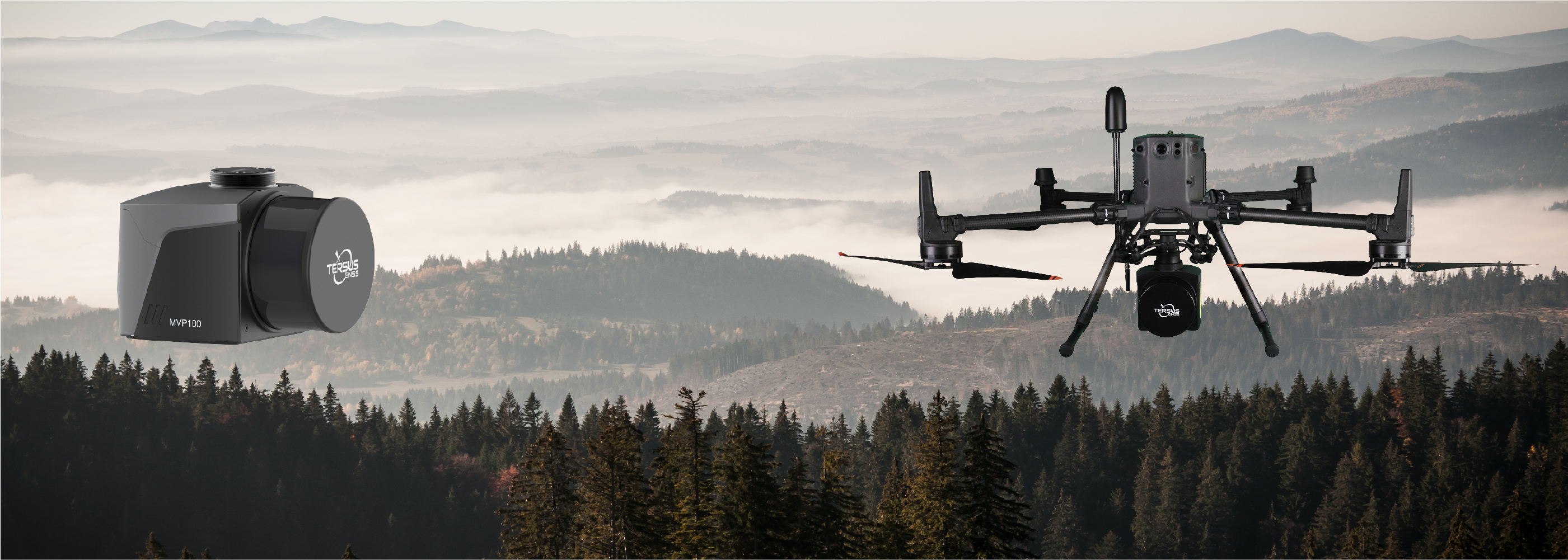
Provide GNSS position and timing inputs for a compatible aerial platform. Flight control and safe operation remain responsibilities of the integrated system.

Select supported RTK or TAP PPP correction delivery. Validate coverage, connectivity and convergence before relying on the positioning output.
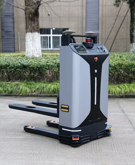
The David Plus forklift case describes GNSS position and heading integrated with third-party control software and additional sensors. It is a complete-platform example.
Read the case study (PDF)Explore the receivers, sensors, field systems and software that support this workflow.
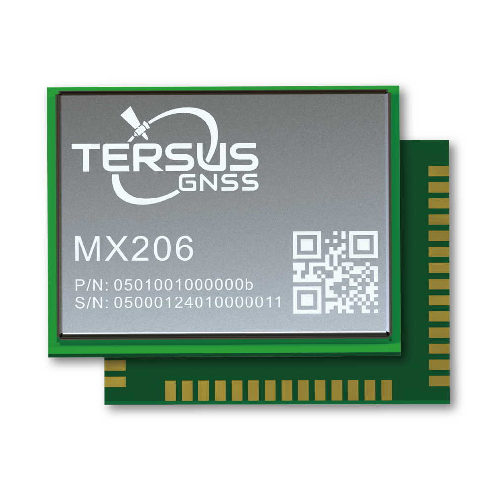
Multi-frequency GNSS module supporting PPP/RTK positioning and TAP corrections for OEM integration.
View Product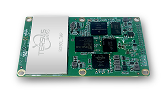
Multi-frequency GNSS OEM board with TAP support for positioning integration.
View ProductGNSS/INS position and attitude input for integrated platforms; performance depends on installation and operating conditions.
View ProductDual-antenna GNSS receiver providing RTK position and heading to an integrated platform.
View ProductMulti-frequency GNSS antenna for positioning hardware in autonomous platforms.
View ProductA practical sequence that can be adapted to the project, environment and deliverable.
Document satellite visibility, dynamics, interfaces, accuracy needs and system responsibilities.
Choose GNSS, inertial inputs, antennas and corrections for the platform architecture.
Configure interfaces and check position, heading and failure behavior in representative conditions.
Monitor receiver status and maintain the complete platform sensor and safety strategy.
Share your environment, accuracy needs and intended deliverable with our team.