Beyond the Spec Sheet: What Truly Defines LiDAR Data Quality?
Peter Yang, Tersus GNSS 24 July, 2025
Why two LiDAR datasets of the same site can look worlds apart, and how to control the variables that matter.
For any professional in surveying, mapping, or engineering, the promise of LiDAR is precision at scale. Yet, we’ve all seen it: one point cloud is crisp, clean, and perfectly aligned, while another of the very same location is noisy, sparse, and plagued with geometric distortions. The spec sheet of the sensor is only where the story begins.
The truth is, exceptional LiDAR data is not an accident. It is the result of a deliberate and scientific approach to the entire workflow, from mission planning to post-processing. It’s about understanding the delicate dance between physics, environment, and geometry.
Let's break down the five critical pillars that govern the quality of every point you capture.
1. The Physics of Reach: Energy, Reflectivity, and the Atmosphere
At its core, LiDAR is a game of signal-to-noise. A laser pulse is sent out, and the sensor listens for its echo. The strength of that returning echo determines whether you get a valid measurement.
• Laser Energy vs. Pulse Rate:Think of a laser's power budget like a bucket of water. You can either pour it out in one strong, far-reaching stream (low Pulse Repetition Frequency, or PRF) or spray it as a fine, dense mist that doesn't travel as far (high PRF). For a long-range survey, a lower PRF delivers higher-energy pulses that can reliably map distant or low-reflectivity targets.
• Target Reflectivity: A concrete surface (high reflectivity) is like a mirror, returning a strong signal. Fresh asphalt or damp soil (low reflectivity) is like black velvet, absorbing most of the laser's energy. This is why a LiDAR system's maximum range is always specified at a certain reflectivity (e.g., 500m @ 20% Reflectivity ).
• The Atmospheric Filter: Fog, haze, and rain act as a filter, scattering and absorbing the laser's energy. This phenomenon, known as atmospheric attenuation, can dramatically reduce your effective range.
In the Field: Before a flight, ask: Am I trying to maximize density or range? Are my targets dark and absorbent? Is the air hazy? Your answers should directly inform your choice of PRF and flight altitude (AGL).
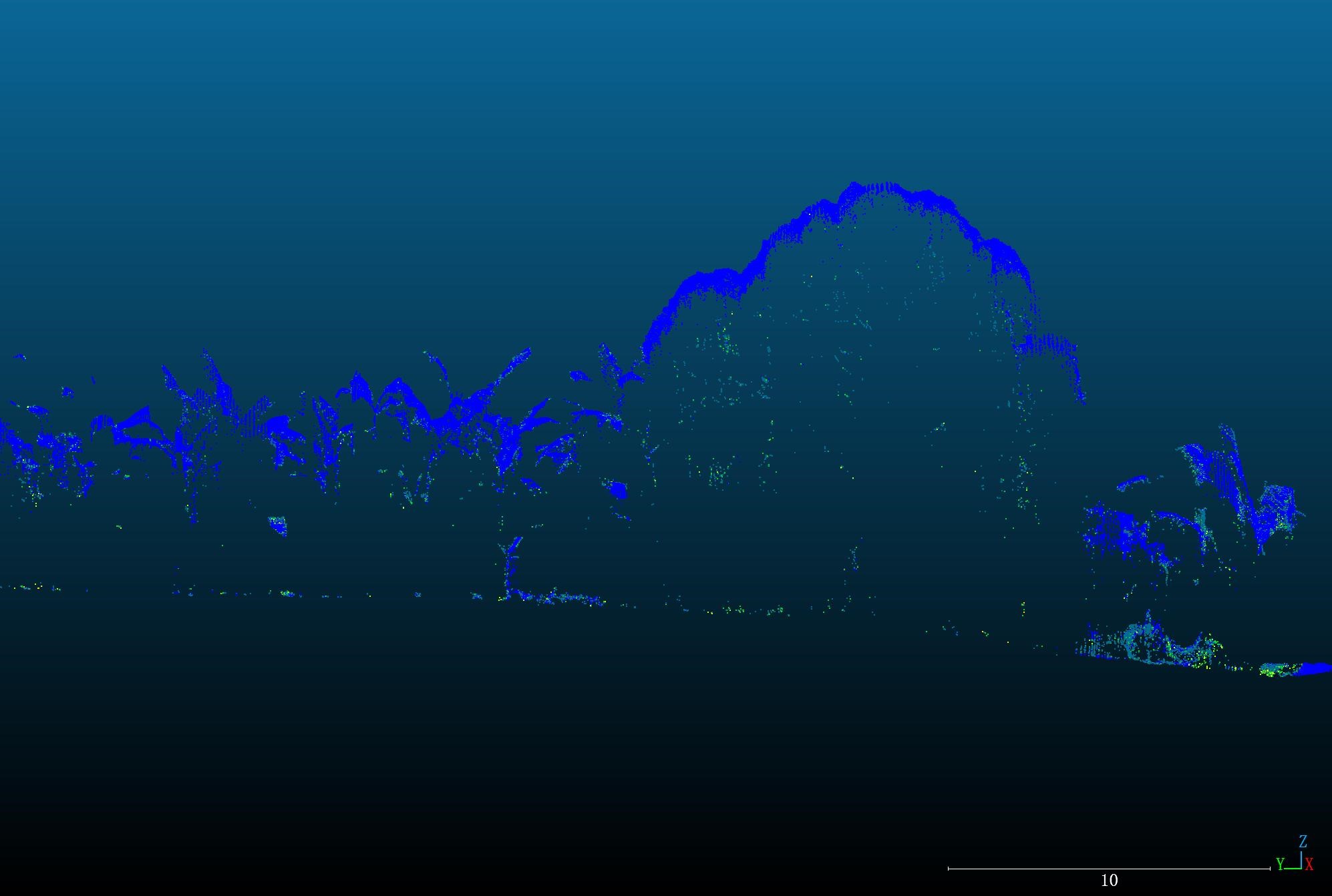
-MVP400-800kHz forest scanning- 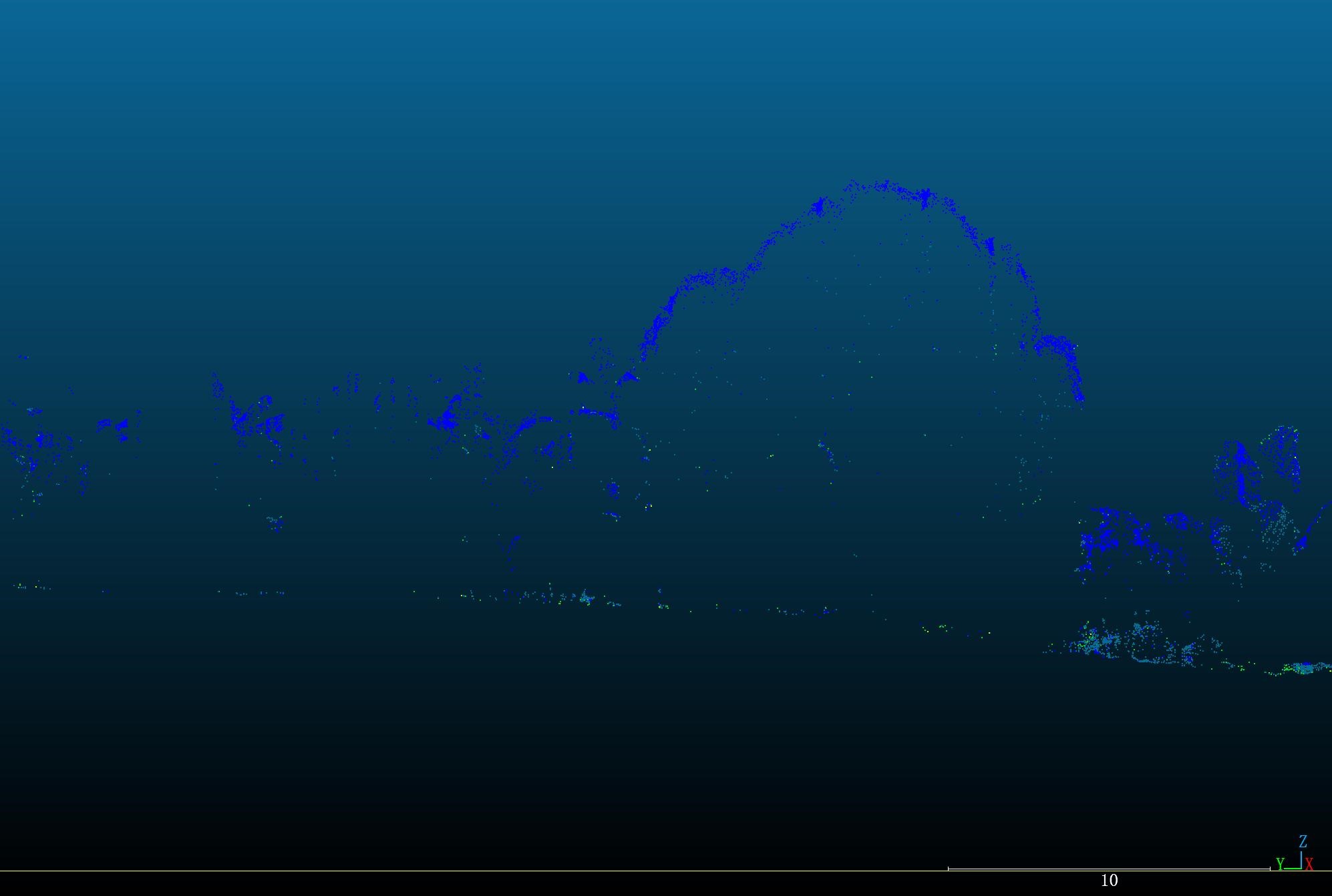 -MVP400-100kHz forest scanning-
2. Penetrability: The Art of Seeing Through the Canopy
For forestry and corridor mapping, the ability to "see" the ground through vegetation is LiDAR's superpower. This isn't magic; it's a function of multi-echo technology.
When a single laser pulse hits a tree, it doesn't just stop. A portion of its energy reflects off the first leaf it encounters (1st return). The remaining energy continues downward, reflecting off lower branches (intermediate returns) until the last, weakest part of the signal hits the forest floor and bounces back (last return).
The key factors for effective penetration are:
• Multi-Echo Capability: The ability of a sensor to record multiple returns from a single pulse is paramount. Modern systems, like the Tersus MVP400 which supports up to 7 returns per pulse, are specifically designed for complex vegetation analysis.
• Pulse Energy and Footprint: As discussed, a stronger pulse (lower PRF) has more energy left to make it to the ground. Furthermore, a lower flight altitude results in a smaller, more concentrated laser footprint on the ground, increasing the energy density and the probability of finding gaps in the canopy.
• Moisture: Wet leaves absorb near-infrared light far more effectively than dry ones. Flying after rainfall will significantly hamper ground returns.
In the Field: To map a forest floor, plan your mission for a dry day. Use a lower PRF to maximize pulse energy, fly at a conservative altitude, and ensure your sensor is configured to record the maximum number of returns. A cross-hatch flight pattern (flying perpendicular lines over the same area) can further improve your chances of hitting the ground from multiple angles. 
3. The Pillars of Precision: GNSS, IMU, and Post-Processing Algorithms
A LiDAR sensor can measure distance with millimeter precision, but this is only one part of the accuracy equation. The final coordinate of every point is determined by a tightly coupled Position and Orientation System (POS).
• Pillar 1: The GNSS Anchor: The GNSS receiver provides the absolute geographic position (X, Y, Z) of the sensor. The quality of this position is the foundation of your project's global accuracy. A robust receiver supporting all major constellations (GPS, BDS, GLONASS, Galileo, QZSS ) is essential for maintaining a strong satellite lock, even in challenging environments.
• Pillar 2: The IMU Attitude: The Inertial Measurement Unit (IMU) measures the sensor's orientation (roll, pitch, yaw) hundreds of times per second. Even a minuscule angular error is magnified by distance (Positional Error ≈ Altitude × tan(Angular Error)). This is why high-precision IMUs, with attitude accuracies reaching 0.008° for Pitch/Roll, are critical for survey-grade results, especially at higher altitudes.
• Pillar 3: The Algorithm's Fusion: The GNSS and IMU data are not enough on their own; they must be intelligently fused. This is where advanced post-processing (PPK) algorithms, like Tersus's proprietary solution, become a critical differentiator. A superior algorithm ensures tight coupling and consistency across the entire dataset. It is the key to eliminating the dreaded data "layering" or systematic drift between adjacent flight lines, guaranteeing a seamless and stable final point cloud.
The Tersus MVP400 embodies this philosophy, integrating a high-performance GNSS/INS module and advanced processing to achieve a vertical accuracy of 3 cm and horizontal accuracy of 5 cm (@150m AGL).
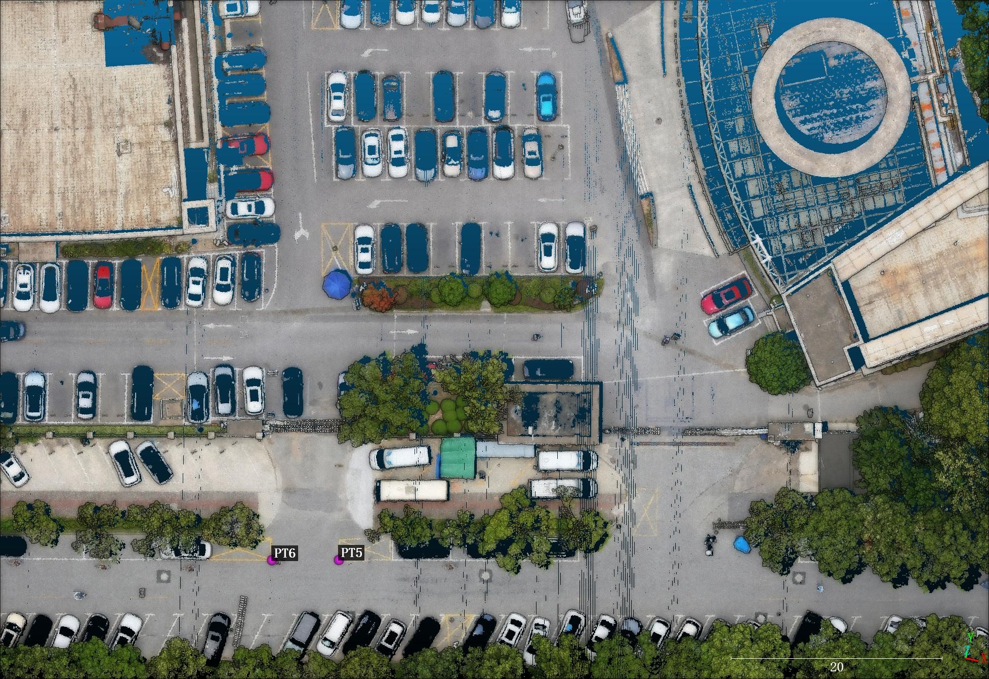
4. Point Density: The Foundation of DetailThe Pillars of Precision: GNSS, IMU, and Post-Processing Algorithms
Point density, measured in points per square meter (pts/m²), determines the level of detail you can resolve in your final data. It is not a measure of accuracy, but it is fundamental to the usefulness of the data. Insufficient density can cause you to miss critical features like thin power lines or subtle ground features.
The density you achieve is a direct result of your mission parameters. A LiDAR's scanner emits a constant number of points per second at a set PRF. Therefore, to increase the density on the ground, you must reduce the area covered in a given amount of time. This can be achieved by:
• Reducing Flight Altitude (AGL): Lowering the altitude concentrates the same number of points into a smaller area.
• Reducing Flight Speed: Slower flight speeds allow the scanner to place more scan lines closer together.
• Increasing Overlap: Higher sidelap between flight lines means each area is scanned multiple times.
• Using a Cross-hatch Pattern: Flying perpendicular lines over the same area significantly increases density and provides more complete 3D geometry of features.
This is where a high pulse repetition frequency becomes a major advantage. A system like the Tersus MVP400, with a PRF of up to 1,000 kHzcombined with a fast scan speed of 300 lines/s, gives operators immense flexibility. You can fly higher and faster for large-area topographic surveys while still achieving sufficient density, or fly lower to generate incredibly dense point clouds for detailed asset inspection.
It's also important to distinguish between theoretical and actual density. Mission planning software calculates theoretical density. However, due to factors like laser absorption by dark surfaces and the generation of multiple returns in vegetation, the final ground point density may differ slightly.
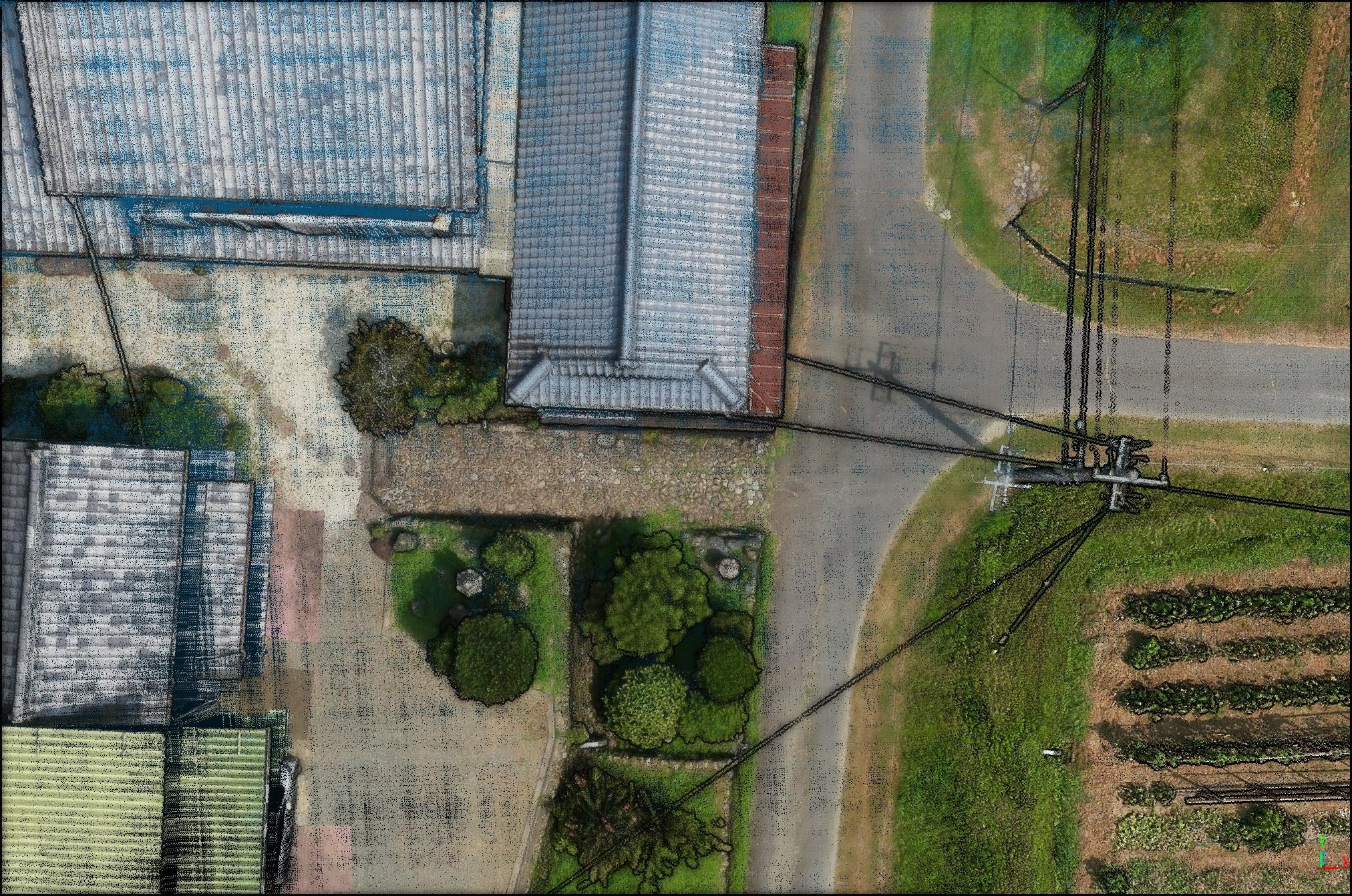
5. Beyond Standard Adjustments: The Power of a High-Fidelity POS Solution
Finally, the quality of a LiDAR system is truly revealed in its raw data, before heavy processing is applied. In the industry, two post-processing steps are common: strip adjustment and point cloud filtering. However, the dependency on these steps often tells a story about the initial data quality.
The Strip Adjustment Conundrum
Strip adjustment is a standard algorithm used to align overlapping flight lines and correct for inconsistencies caused by residual drift in a system's POS (Position and Orientation System) solution. While it is a necessary tool for many, the ultimate goal should be to minimize the need for it. This is where a high-fidelity POS solution, born from the synergy of a survey-grade IMU and advanced, self-developed GNSS algorithms, changes the game. By ensuring the highest possible precision in the initial trajectory, the Tersus solution generates a raw point cloud that is exceptionally precise and consistent from the moment it is created. This drastically reduces the dependency on aggressive strip adjustments and ensures that what you see is a true reflection of the sensor's measurement, not an algorithmic approximation.
The Pitfall of Over-Filtering
A similar principle applies to point cloud filtering. Some processing software employs heavy filtering to make the final point cloud appear artificially "thin" or less noisy. While this can create a visually clean result, it often comes at a high cost: the smearing of fine details. Sharp corners on buildings, curbs, and other critical features can become rounded and lose their real-world definition—a disastrous outcome for high-precision surveying.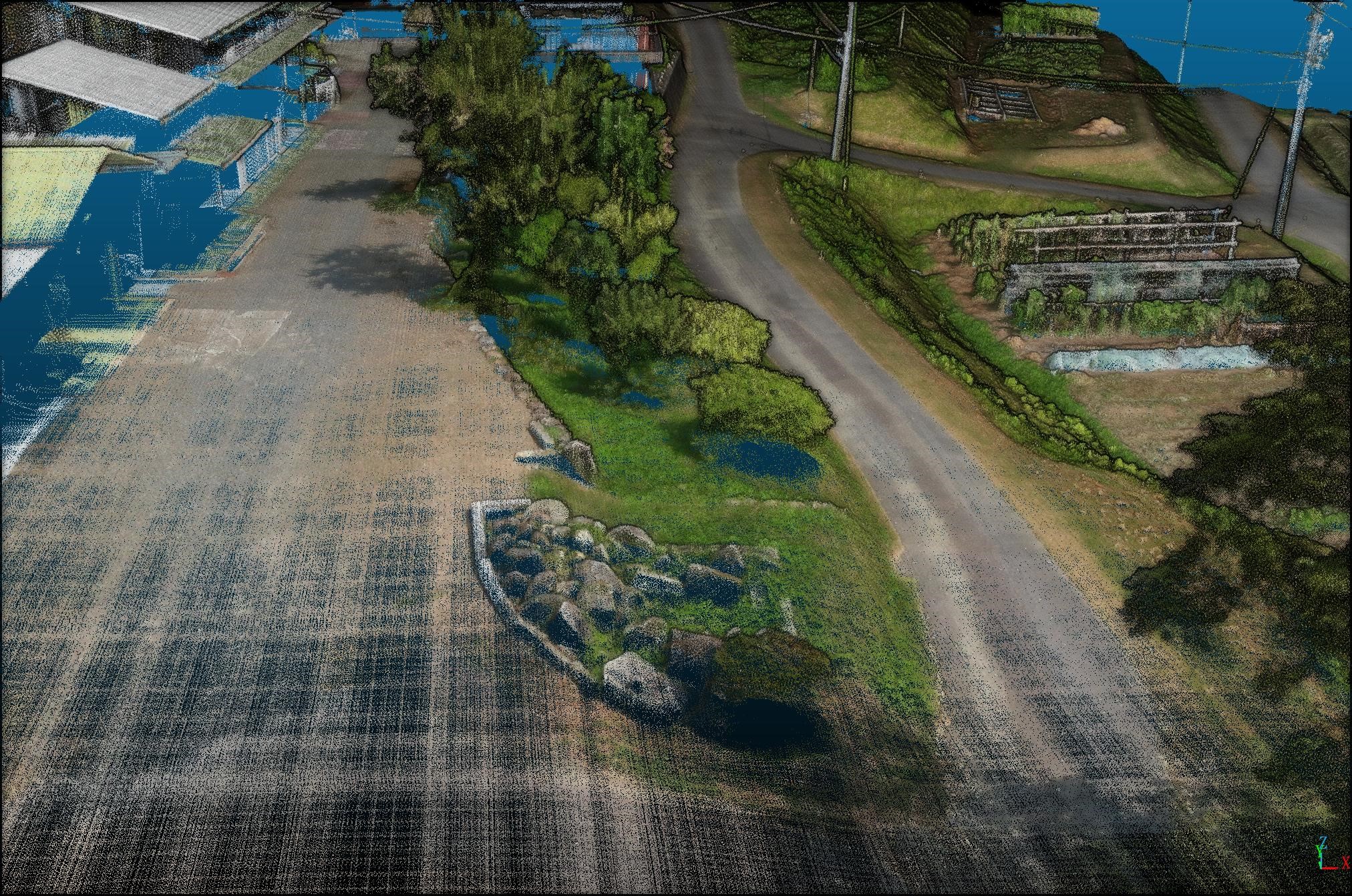
The Tersus MVP400, by contrast, relies on the integrity of its source measurements. Equipped with a high-quality laser boasting a ranging accuracy of 5 mm, the system captures exceptionally clean and precise data points from the start. This allows our processing suite to preserve the authentic geometry of the scanned environment, delivering point clouds with remarkable clarity and sharp, well-defined details, even with minimal or no filtering applied.
Conclusion: From Operator to Expert
Understanding these principles transforms you from a system operator into a data expert. It allows you to look at a project site—its terrain, vegetation, and environmental conditions—and make intelligent decisions that directly impact the quality of your final deliverable.
High-quality LiDAR is not about pushing buttons; it's about mastering the interplay of energy, geometry, and environment. When you have hardware engineered for precision and the knowledge to deploy it effectively, you can deliver results that aren't just good—they're authoritative.
About Tersus GNSS Inc.
Tersus GNSS is a leading Global Navigation Satellite System (GNSS) solution provider. Our offerings and services aim to make centimeter-precision positioning affordable for large-scale deployment.
Founded in 2014, we have been pioneers in design and development GNSS RTK products to better cater to the industry’s needs. Our portfolios cover GNSS RTK & PPK OEM boards, David GNSS Receiver, Oscar GNSS Receiver, MatrixRTK [GNSS CORS Systems] and inertial navigation systems.
Designed for ease of use, our solutions support multi-GNSS and provide flexible interfaces for a variety of applications, such as UAVs, surveying, mapping, precision agriculture, lane-level navigation, construction engineering, and deformation monitoring.
Sales inquiry: sales@tersus-gnss.com
Technical support: support@tersus-gnss.com
